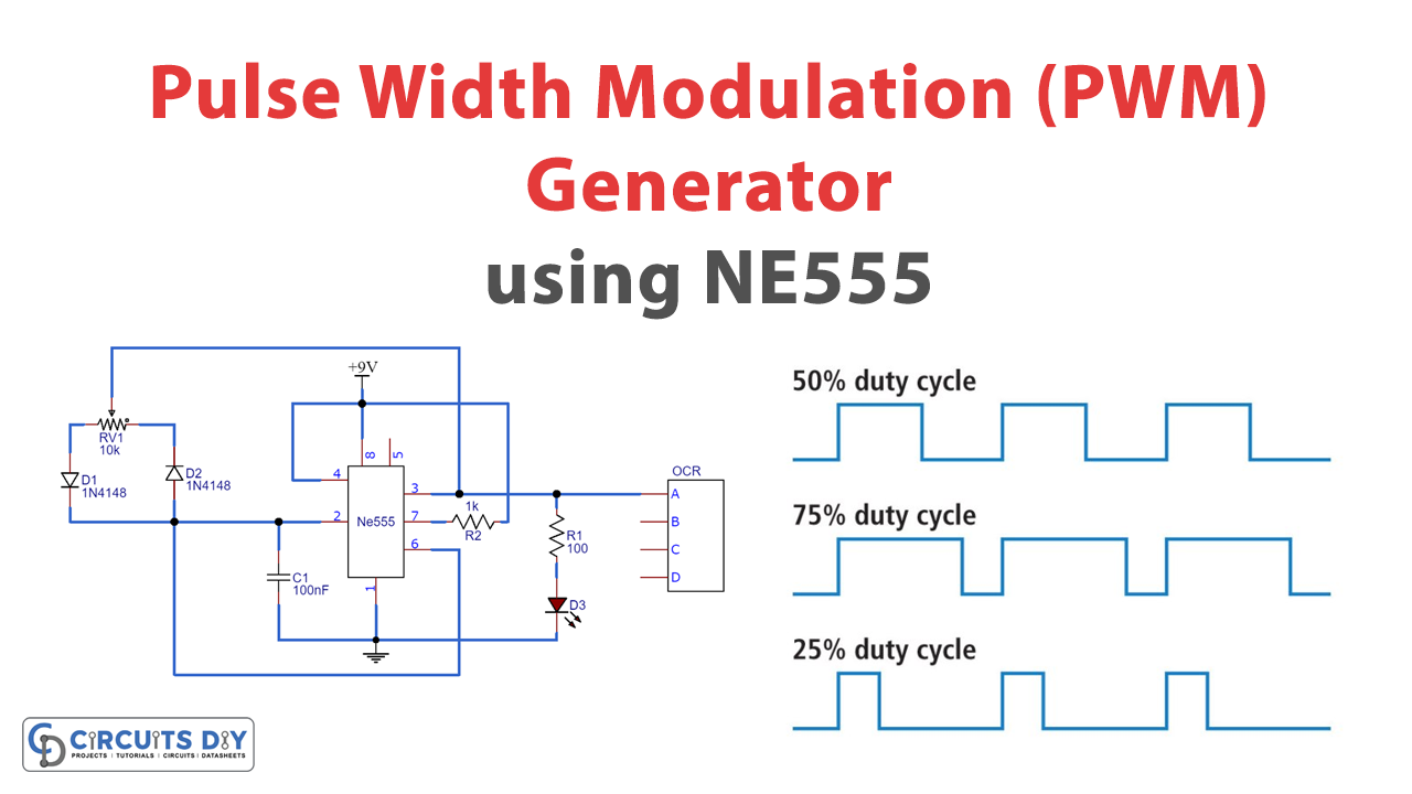
Generate Pulse Width Modulation PWM Signal using 555 Timer IC Circuit Diagram The output is taken from the usual pin#3 of the chip. In the above straightforward configuration the IC 555 is all set for generating the required PWM pulses, it just requires a square wave pulse or a clock input at its pin#2, which determines the output frequency, and a variable voltage input at pin#5 whose amplitude or the voltage level decides the pulse width dimensions at the output.
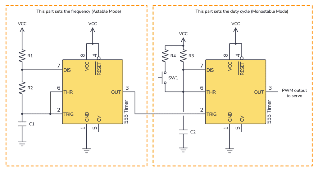
Working of the PWM Based DC Motor Speed Controller. The 555 Timer is configured in its astable mode, which means it will oscillate continuously between its high and low states, producing a square wave output.The frequency and duty cycle of this square wave (PWM signal) are determined by the resistors (R1, R3) and capacitors (C1, C2) connected to the 555 Timer.

555 Timer PWM Controller - Techatronic Circuit Diagram
Basic (PWM) Motor Speed Control Using 555 Timer ICs: This is the first part of supposed to be a two-part instructable about speed control of a DC motor using 555 timer ICs meant to cater those who are still starting to make electronics a hobby and beginners like me in a way. Based on this findings, we need to create a resistor configuration
In this 555 timer project, I have shown how to make PWM DC Motor Speed Controller circuit using 555 Timer IC on homemade PCB. With this dc motor controller c 555 Timer PWM Generator Circuit. The 555 Timer is capable of generating PWM signal when set up in an astable mode. In you are not familiar with the 555 Timer you can check my previous tutorial where I explained in details what's inside and how the 555 Timer IC works.. Here's a basic circuit of the 555 Timer operating in an astable mode and we can notice that the output is HIGH when the

How to Generate PWM Signal using 555 Timer IC? Circuit Diagram
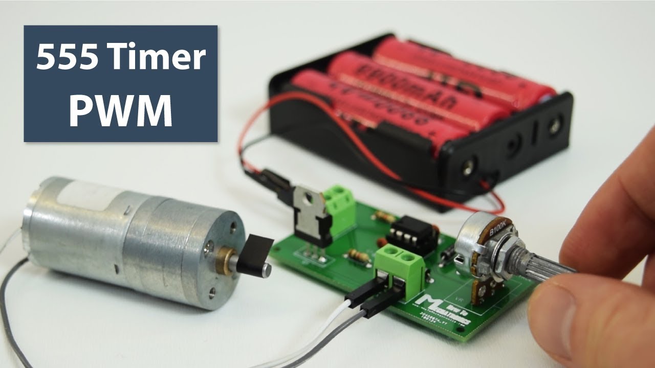
The 555 timer ic is known to make the oscillation which results in generating the square wave. and with the help of the 555 PWM circuit, we will modify the width of the pulse by using a potentiometer. when you rotate this potentiometer the speed of the motor will change according to the potentiometer. In this video, I demonstrate how to build a simple yet effective PWM (Pulse Width Modulation) circuit using the versatile 555 timer IC. This circuit allows y In this tutorial, you'll learn how to build a 555 PWM Circuit. The 555 timer is one of the most popular integrated circuits for hobbyists. And one of the cool features is its ability to produce a PWM signal. The circuit is fairly easy to make, and it can control a great variety of things, including motor speed and LED brightness.