Low pass filter Op Circuit Diagram Step-by-step design of Active low pass filter using Op Amplifier. Hi, thanks for watching our video about active filters! In this video we'll walk you through:- How to design, simulate and build active opamp filters- Using
Second-Order Active High-Pass Filter. If we swap the resistor and capacitor in an RC low-pass filter, we convert the circuit into a CR high-pass filter. We can then cascade two CR high-pass filters to create a second-order CRCR high-pass filter. If we incorporate this passive configuration into the Sallen-Key topology, we have the following:
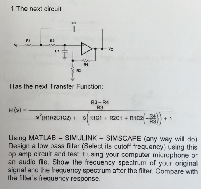
Pass and Active High Circuit Diagram
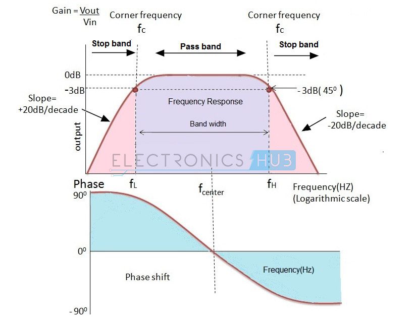
Key learnings: Active Low Pass Filter Definition: An active low pass filter allows low-frequency signals to pass while blocking higher frequencies, essential for various electronic applications.; Component Significance: The use of an operational amplifier (Op-Amp) is critical for adjusting frequency response and enhancing signal quality.; Filter Design: Active low pass filters can be designed

range. Bessel low-pass filters, therefore, provide an optimum square-wave transmission behavior. However, the passband gain of a Bessel low-pass filter is not as flat as that of the Butterworth low-pass, and the transition from passband to stopband is by far not as sharp as that of a Tschebyscheff low-pass filter (Figure 16- 9).

Active Low Pass Filter: Design and Applications Circuit Diagram
When used like this in audio applications the active low pass filter is sometimes called a "Bass Boost" filter. Second-order Low Pass Active Filter. As with the passive filter, a first-order low-pass active filter can be converted into a second-order low pass filter simply by using an additional RC network in the input path. The frequency View full article: https://www.allaboutcircuits.com/video-tutorials/op-amp-applications-low-pass-and-high-pass-active-filters/In this video we will explore a